1300 737 976
Call us
Live Chat
Call us
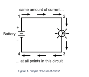
In our electrical education days when we learned basic electrical theory in conjunction with Ohm’s Law, we learned that DC current is equal and constant in a simple series circuit represented by a closed loop. Voltage was a different situation. Depending on resistances in that simple series circuit, the voltage would vary at different points.

The common DC current transmission standards are 0-20mA or 4-20mA where 4-20mA is by far the most prolific.
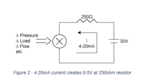
Why 20mA signals I hear you say? A simple explanation is that in the pre-digital era when analogue devices were prolific, an analogue input channel expected to see a maximum 5V signal. An external precision resistor (or “shunt”) was placed across the input to create a voltage when a current was passed through. These resistors were typically 250Ω. To get 5V to appear across a 250Ω resistor, a current of 20mA is needed. There you go.

Another key benefit of 4-20mA signals is that the power used to drive the signal around the circuit can also be used to power a special low energy sensor connected at the remote end of the circuit where the sensor does the measuring. This isn’t possible with 0-20mA signals as 0mA means no power. We need at least 4mA to keep the sensor powered and functional. These sensors are referred to as “loop powered”.
Most electronic devices would need two wires for power and another 2 wires for the signal. One of the benefits of loop powered powered circuits is that only two wires are needed (single pair cable). The same wires that carry the signal also power the remote sensors. This halves the amount of wires needed or where existing wires exist already, it means that no new wires have to be run in the factory which would be time consuming and costly.
Just remember, the loop powered 2-wire system must be 4-20mA. Surprisingly, people do ask suppliers for 2-wire sensors with 10V DC outputs. This isn’t possible.
Connecting loop powered circuits is quite confusing to many.

Think of the positive terminal as where the current enters the device after leaving the power supply. Connect the “ins” and “outs” in sequential order.
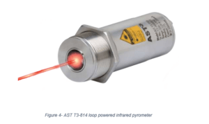
Advances low power electronics have enabled loop powered sensors to provide additional benefits such as backlighting of LCD digital displays and even to power laser aiming systems such as that found on loop powered infrared temperature sensors!
Pyrosales engineers are available to consult on various stages of any project, from the development and planning of a new project to modifying or upgrading an existing facility. Our staff is here to provide you with assistance and recommendations to ensure the best outcome and value. We are happy to visit our clients on-site or conduct meetings from one of our offices.
Copyright © 2022 Created by Pepper Digital
Disclaimer – Images for illustrative purposes only and may not be representative of the actual resolution of the camera shown.